My
DIY Pages
Home > Studio
Recording DIY Projects > SC-1
Mic Preamp Kit
|
NEW!!! SC-1
Mic Preamp Kit
Status: Under Development:
Noise
Obsession
I've
been pondering this noise issue for
a couple of days now.
......
so last night, I'm trying to review
my design and reviewing the data
sheets....
I
*KNOW* I have the resistor values
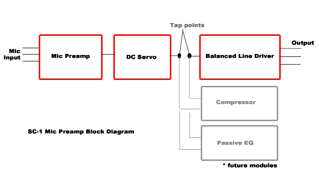
for the mic pre stage I have were
computed for 0 to 66dB gain. Then
it goes to a servo, then to an unbalanced
to balanced line driver.... which
then goes to the MOTU inputs.
So
I'm thinking... maybe it's the line
driver stage giving me the noise
problem??? The 1510 chip.
So
I looked at the datasheet and something
caught my eye.... the line driver
stage ADDS ANOTHER 6dB GAIN!!!! DUHHHHH!!!!
Of course! Going from unbalanced
to balanced, gives you an additional
+6dB gain!
So
really, my preamp does not go from
0-66dB in 12 steps, BUT RATHER it
goes from +6 to +72dB gain!!!! (i.e.
66dB mic pre gain + 6dB gain of balanced
driver = 72dB total gain!)
So
the correct noise figures compared
to dB gain are:
| Noise
Floor at max gain settings,
max volume, 150 ohm terminated
inputs |
6dB
= -90dB*
12 dB = -90dB*
18 dB = -90dB*
24 dB = -90dB*
30 dB = -90dB*
36 dB = -90dB*
42 dB = -88dB
48 dB = -85dB
54 dB = -80dB
60 dB = -74dB
66 dB = -69dB
72 dB = -64dB |
So
there you go!
The
FINAL SCORE!!!....
-69dB
@ 66dB Gain with Rs=150 ohm terminated
inputs, volume at max 100%. Which
is about comparable to the RNP's
noise floor and other non-transformer
based IC mic pre design.
And
for the icing on the cake, mine can
go up to 72dB of gain, not just 66dB!!!
-64dB @ +72dB gain (which is 4000x
amplification!)
Not
bad!
|
|
Found an oscilloscope plugin...
http://mdsp.smartelectronix.com/ffttools/2005/03/freakoscope-08-public-beta.php
continuing with this noise obsession... using the above
plugin.
Since a picture is worth a thousand words.


INSERTS
The SC-1 has one feature that I have not talked about
much. It's got provisions for an INSERT.
Just like the Inserts in your mixer, the concept is I
want to be able to add future signal processing to the
SC-1 easily.
I envision in the future creating add-on modules to the
SC-1. For example: Passive EQ, Active EQ, optical compressor,
VCA compressor, etc... so all you'll need to do is solder
3 wires, remove the jumper JP2 and the add-on module
is now part of the signal path.

If you're a purist, and you don't want anything else changing
the sound... just don't add any modules.
If you want a preamp with an EQ, you can have it.
If you want a preamp with built-in compression, you can
have it.
If you want THE WORKS, preamp with built-in compression,
EQ, etc...
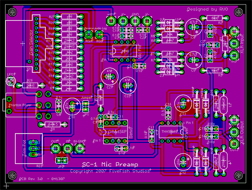
Just add the modules you want. You can see the 3 solder
pads in the PCB in the photo below, near the lower left
corner.
As
far as the insert modules go, would it be possible
to wire this as a 1/4" insert jack?
I
looked into the datasheets, and it could work.
The SC-1 will have a 5K input impedance for the insert
return. And the send can have a max +/- 13V swing (on
a 15-0-15 supply) output voltageon a 2K load.
Note: the SC-1 will be powered by 18-0-18 so the output
voltage swing could be higher.
(The Mackie 1402VLZ has 2.5k input impedance for the insert
return. )
I'll
try it out one of these days.
UPDATE : Rev3
PCB went into prototype manufacturing - 4/18/2007

Good news! We're almost there! I sent Revision 3 PCB to
the manufacturer today for a 5 pc prototype run. We'll
see in 5 days how it turns out.
When I receive the PCB back, I'll build prototype #003
and #004 for further testing.
To
be continued...
|


