My
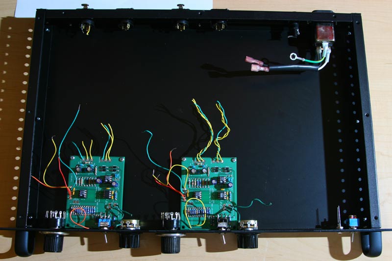
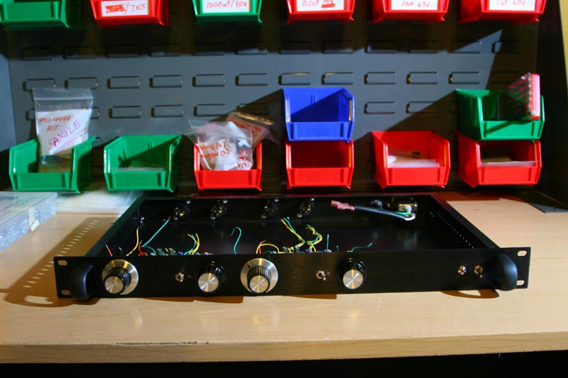
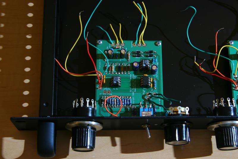
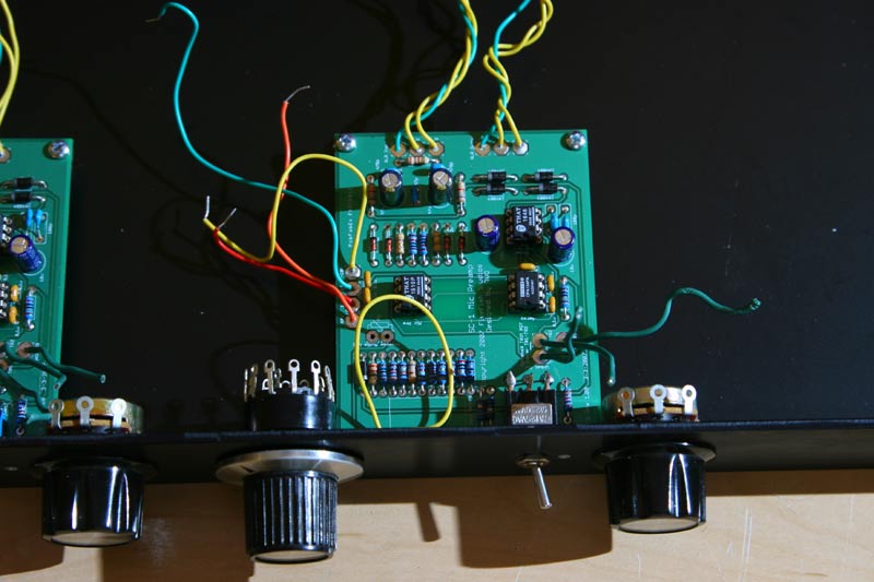
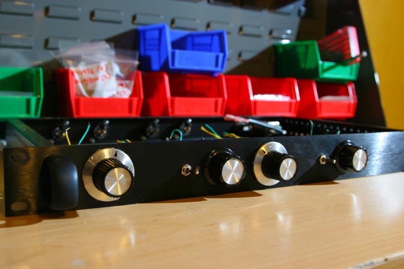
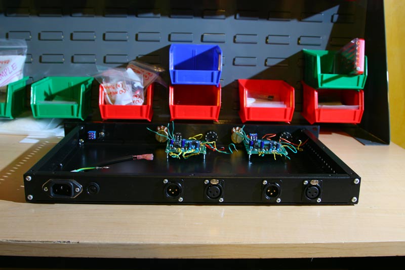
DIY Pages April 20, 2007 I'm racking prototype #001 and #002. Getting ready to use it for sample recordings, so I need to be able to take it anywhere easily. I'd also like to see if racking it in a metal case will improve noise floor further... hope so!!! Also going to test how the 7818/7918 PSU type regulators stack up vs. 317/337 type regulators. I want to see if 317/337 are really better than plain stock 7818/7918, or if it's just a myth. This is still the PCB without the onboard pots and selectors. So I guess, we'll also see noise performance when using external pots and switches with hook-up wires. Here are some photos.... sorry for the harsh shadows, I just used a single flash on the right side and didn't use any reflector on the left. If you use on-board pots and switches, you can easily fit 4 preamp channels on a 1u rack... with plenty of room to spare in the back. http://www.fivefish.net/diy/sc1/images/protocase2.jpg The front view of the prototype rack. (On the background, you'll see my new "electronics assembly" factory. I'm getting ready to package some PSU kits to sell.) Closeup of prototype #001.
The switch you see in the picture is just a jury-rigged DPDT switch using component leads soldered to the switch and PCB. Closeup of prototype #002.
Knobs and switches and pots on front panel. Back view showing IEC AC line filter connector, fuse, and Neutrik XLR male and female jacks.
I'll wire this puppy tomorrow.
|

