Home > Studio Recording DIY Projects> Unbalanced to Balanced Line Converter
This circuit will convert unbalanced audio lines to balanced audio lines.
Here's the schematic
diagram using NE5532 dual opamp chips, some resistors and capacitors.
Tested the circuit on a breadboard.
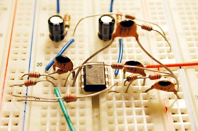
It works!
We all know that balanced lines have less susceptibility to noise, especially on long distances. This is common knowledge.
But I'd like to point out one more benefit of balanced signals that I just realized this afternoon. And that benefit is you'll have 6db more gain in a balanced signal compared with the original unbalanced signal!!! Mathematically, we know it would happen, but seeing it as a real waveform in Sonar is proof of concept.
What's the
big deal about 6db gain?
6db of gain is DOUBLE the signal strength... which means, your signal
is going to be hotter, without any changes in your setup. Thus, you don't
have to increase your preamp/mixer's gain as much to achieve a good loud
level, and since the signal increased by 6db, it also goes into saying
that you just reduced your noise by 6db too, i.e. you also reduced noise
by half.
*My opinion speaking*...
You see, MOST gear are really unbalanced inside. They just have balanced
drivers at the output stage. And some mastering engineers (read Bob Katz's
book) prefer unbalanced gear ( yeah, I was shocked to hear this). His
reasoning that since all the gear are plugged in one room anyway, and
the inside circuitry of gear are almost always unbalanced, and depending
on how the balanced circuit driver was made, could degrade the signal,
etc... This guy knows electronics and his statement actually makes sense.
But he also said that there are some truly balanced circuitry where you can't take away any part out, and these are almost always the best kind of gear. (More on this below.)
Back to the topic... the circuit above can be added to any unbalanced out and make it balanced. The 2 driver opamps drive each half of the signal, one being 180-degree inverted. In this case, the rejection of EMI and RFI is between the lines of the balanced input and output gears.... not within the gear itself. If you can isolate the unbalanced-to-balanced driver circuit in a device and the device can still work, then that device is really unbalanced.
The Neve preamp schematic on the other hand is a different beast. From the input transformer, all the way to the output transformer, it is balanced. i.e. I can't take away the output transformer and still have this functioning right. I can't take away the input transformer and still have it functioning. The input and output transformer makes this gear have balanced inputs and outputs, and the supporting circuitry inside relies on connecting to these transformers to do its job.
Note:
The
above circuit is an ACTIVE balanced driver. i.e. it requires power.
There are other ways of achieving a balanced output and that is through the use of output transformers.... See Jensen-transformers.com website for their application notes.
Of course, now we're talking about spending $75 to $90 just for the cost of the transformer PER CHANNEL! Compare that to about less than $3.00 for the circuit above.
Now you know why most manufacturer's don't use audio transformers anymore, and the few ones that still use them sell gear in the $1,000+ range!
Here's the frequency plot of my unbalanced to balanced coverter. Pretty good even though it's sitting only on a breadboard.