Home > Studio Recording DIY Projects> KRK RP8 Electronics
KRK RP8 Autopsy
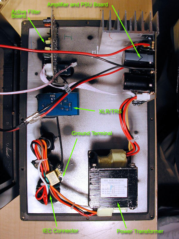
Here's a bird's eyeview shot of the back panel. You can see how big the transformer they used for the RP8. The heatsink for the amps are not humongous, but don't forget, it's attached to the back plate with thermal plate and screws, so the back plate also acts like a heatsink to help dissipate heat away from the amp chips.

Note that the amplifier board (upper right) with the heatsink is also the Power Supply board. That's right... the amplifier and the power supply are on the same PCB.
The secondary windings from the transformer, see lower right, (red, red, black, yellow, yellow) are connected to the amplifier/psu board.
There is a white ribbon cable that connects the amplifier board and the active filter board.
It carries 18V-0-18V DC voltage from the Amp/PSU board to the active filter board. This is necessary to power the opamp chips of the Active filter board. From the active filter board, it sends LF, HF, and signal ground back to the amplifier board.
The picture below shows where the ribbon cable is attached to the filter board. Notice that there is a pin labeled "ST BY."
This is a stand-by pin. The amplifier chips have pins labeled stand by that control whether the amplifier turns on or off. More on this later....

And then from the amplifier board, you have wires going to the woofer and tweeter, and the Yellow LED power on light.
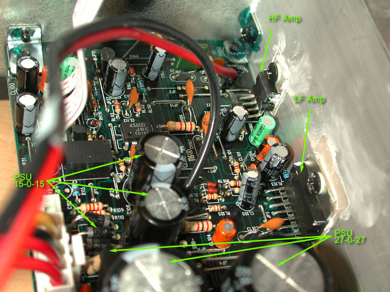
One thing I notice is the PSU is NOT regulated. There are two power supply voltages running on the PSU, and both uses bridge rectifiers and 2 capacitors. No regulation.

Looking at the above picture, you can see the 2 amplifier chips. The smaller chip is for the tweeter, and the bigger chip is for the woofer.
You can also see a whitish dried up paste around the chips and smudge around the heatsink. This paste is used to attach the Mica insulator and assure good heat conductivity to the aluminum heatsink. It's a little sloppy in my personal opinion.
You can also see a 4580 chip in the tweeter section. I'm not sure if this is another high-pass filter.
You can also see (2) mid size capacitors (1000uf/35V) and (4) diodes that comprise the 18-0-18V PSU.
Partially seen (and blurred) are two bigger capacitors rated 4700uf/50V for the 27-0-27 V PSU that powers the big amplifier chip.
Next Page... More Amplifier Board Pics
.