Home > Studio Recording DIY Projects>PM1001 Mic Preamp
Next
step:
Determine values of stepped attenuator for mic preamp... adjustable gain
selector switch from 5dB to 65dB.
Testing:
Max output gain is 47dB at current design. To achieve 70+dB gain, I will have to add another circuit stage with additional 2 transistors.... we'll see if I'm up for it.... or reserve that for version 2... don't know yet. (Which means, I'd have to redesign the PCB again, arrrgghh)
Problem: The Sowter transformers I use oscillate badly at max gain if not terminated. But if i terminate them with a 600ohm load to fix the oscillation, I can hear a slight degradation of the high freq sounds. Using a different output transformer didn't have this problem so I may have to ditch the Sowter output trafo and use a different brand/model. I ordered a different transformer and we'll see if that fixes the oscillation problem.
Progress is kinda slow right now... while I spend time debugging this.
My Bad
Found a resistor inserted in the wrong location.... my handwriting made R25 look like R28. Because of this error, I wasn't properly biasing the 1st stage mic preamp. Got rid of the wrong resistor, put in the correct value and it now sounds better (high freq especially at low volume levels).
.... which means I'll have to redo all my tests again!!!! Arrrgghhh.
New Tests after fixing My Bad
I was getting dissapointed with this project during the past few days... too many problems going on and I had second thoughts of continuing it...
Yesterday, the breakthrough of finding a component inserted in the wrong location gave me hope and could be the culprit to all my past problems.
So I did new tests and here are the results...
Conditions:
Running @ 40VDC supply voltage
Input voltage: 16.81 mV rms
Measured output voltage (before signs of any clipping):
8.9 Vrms (12.59 Volts peak-to-peak; i.e. headroom)
dB
gain = 54.47 dB (WOW!)
Max Output: +21.20 dBu
Things are looking better. There's still oscillation going on when using the Sowter output transformer.... so that issue is still up in the air.
Continuation of the Saga
Looking even better today!
For the past 2 weeks, I've been struggling with problems on my prototype.
First, I can't use my output transformer because it oscillates at max output.
Second, I found out I inserted the wrong part in the wrong location, and that kinda messed up the sound. I fixed that.
While there was remarkable improvement in sound and output gain after fixing the above problem, I still wasn't happy. It seems to sound distorted at high frequencies.
Looking at the oscilloscope, I can see it was ugly... really UHHGGGLY. Ugly waveform, ugly reproduction of sound.
It got to the point of me thinking of scrapping the whole project. I don't want to sell a junk-sounding kit to you guys.
Well, guess what??!!!! I fixed the problem!!!!

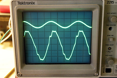
Here's a BEFORE screenshot of a 40Khz waveform. (Yes, 40Khz!) Above is the
input waveform, at the bottom is the preamp output. Notice the jagged
edges.... Looks like the Himalayan mountains. Bad bad bad.

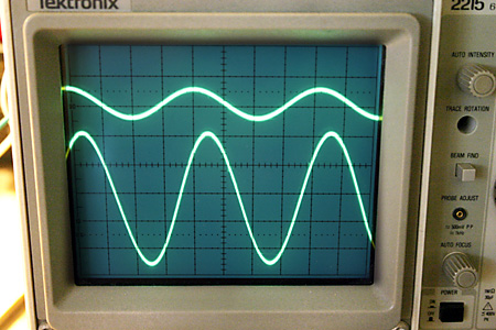
And here's the AFTER shot after fixing the problem... looking good even at
40 Kilohertz! Notice the output waveform is Smooth... very nice.
No problems reproducing 40Khz! I went down to 10Hz, and it also looks
good. icon_smile.gif
I passed some audio signals, connected it to my speaker, and WOW... it now sounds even better. It sounds BIG, it sounds clean, the high frequencies and the delicate nuances are preserved. We're back in business!
I will have to modify the schematic, add my fix and changes, and redesign the PCB again to incorporate my fix. But things are looking very very good today.
